Showing posts with label Mechanics of Materials-1. Show all posts
Engineering Mechanics Lab
By : Asad Ali Arshad |
| Engineering Mechanics Lab |
Rack-Pinion animation.mp4
null
Worm Gear.mp4
null
Cam and Follower Mechanism in Engine - Magic Marks_2.mp4
null
Cam and Follower.pptx
null
Rack-Pinion animation.mp4
null
How Bevel Gears Work.mp4
null
Gear Train Mechanism.pptx
null
Mechanics of Material
By : Asad Ali Arshad |
| Mechanics of Material Chapter no 6 |
Mechanics of Material
6_shearing_stresses.pdf
null
Chapter no 6
Shearing Stress in Beams and Thin Walled Members
In this we will discussed the following topic and these topics are discussed in detail in the above given slides.
Introduction
Transverse loading applied to a beam
results in normal and shearing stresses in
transverse sections.
Distribution of normal and shearing
stresses satisfies.
When shearing stresses are exerted on the
vertical faces of an element, equal stresses
must be exerted on the horizontal faces.
Longitudinal shearing stresses must exist
in any member subjected to transverse
loading.
- Shear on a horizontal face of a beam
- Solved Example Problem 6.1
- Determination of Shearing Stress in a Beam
- Shearing Stress in Common Types of a Beam
- Solved Example Problem 6.2
- Shearing Stress in Thin Walled Members
Mechanics of Material
By : Asad Ali Arshad |
| Mechanics of Material Chapter no 5 |
Chapter no 5 : Mechanics of Material
Analysis and Designs of Beam for Bending
In the above slides we will discussed this chapter in detail and solved some of the conceptual questions.
We will cover the following topics of this chapter
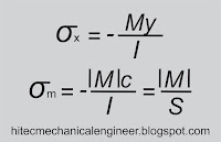
A safe design requires that the maximum normal stress be
less than the allowable stress for the material used. This
criteria leads to the determination of the minimum
acceptable section modulus.
Among beam section choices which have an acceptable
section modulus, the one with the smallest weight per unit
length or cross sectional area will be the least expensive
and the best choice
We will cover the following topics of this chapter
Introduction to this chapter
Objective - Analysis and design of beams
• Transverse loadings of beams are classified as
concentrated loads or distributed loads
• Applied loads result in internal forces consisting
of a shear force (from the shear stress
distribution) and a bending couple (from the
normal stress distribution)
• Normal stress is often the critical design criteria
 |
| Bending moment |
Requires determination of the location and
magnitude of largest bending moment.
Classification of Beams
Shear and Bending Moment Diagram
- Determination of maximum normal and shearing stress requires identification of maximum internal shear force and bending couple.
- Shear force and bending moment at a point determined by passing a section through the beam and applying an equilibrium analysis on the beam portions on either side of the section.
Solved Sample Problem 5.1
Solved Sample Problem 5.2
Relation between load shear and bending moment
Solved Sample Problem 5.3
Solved Sample Problem 5.4
Design of prismatic beams for bending
The largest normal stress is found at the surface where the
maximum bending moment occurs.
 |
| Bending Moment |
less than the allowable stress for the material used. This
criteria leads to the determination of the minimum
acceptable section modulus.
 |
| Section Modulus |
chap-5.pdf
null
Among beam section choices which have an acceptable
section modulus, the one with the smallest weight per unit
length or cross sectional area will be the least expensive
and the best choice
Solved Sample Problem 5.8
For more detail download the above slides..
Hitec Mechanical Engineering
Mechanical Engineeirng Hitec Mechanical Engineering As we know Mechanical Engineering is the branch of engineering dealing with the des...


